 HOME > Research > ReRAM Device & Array Application
ReRAM Device & Array Application
ReRAM device and array application
- ReRAM can be applied to various applications by using the device's unique characteristics or crossbar array (CBA) characteristics. Representatively, CBA can efficiently perform MAC operations in parallel based on Kirchhoff's law and Ohm's law and thus can be applied to operations such as deep learning. Meanwhile, using the characteristics of the ReRAM cell itself, research such as reservoir computing and the temporal kernel can be performed, and graph algorithms can be performed using the unique properties of CBA.
1. Kernel application of eBRS RRAM device
1-1) Nonvolatile memristor-based temporal kernel- Recent advances in physical reservoir computing (RC), which is a type of temporal kernel, have made it possible to perform complicated timing-related tasks using a linear classifier. However, the fixed reservoir dynamics in previous studies have limited application fields. In this study, temporal kernel computing was implemented with a physical kernel that consisted of a W/HfO2/TiN (WHT) memristor, a capacitor, and a resistor, in which the kernel dynamics could be arbitrarily controlled by changing the circuit parameters.

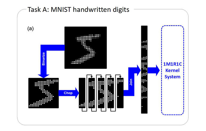
- Figure a shows the TK system that can control the kernel dynamics using a memristor, a normal resistor, and a capacitor (1M1R1C). This is a structure in which the reservoir is replaced with a 1M1R1C temporal kernel while maintaining the computing scheme of the RC system. In this TK system, the charging and discharging of the capacitor transforms the signals applied to the device into various forms so that the conductance state of the memristor can be varied depending on the magnitude and sequential arrangement of the input signal. The results of input processing in the kernel form a memristor conductance vector (MCV), which becomes the input of the subsequent FCN readout layer. Figure b shows the measured current-voltage (I-V) curve of the WHT device.
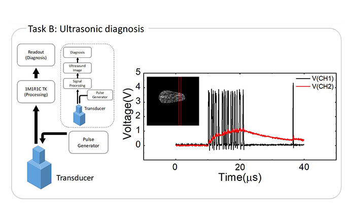
- TK system was adopted to recognize the sequential data (MNIST image recognition, Task A), ultrasound (malignancy of lesions, Task B) and electrocardiogram (arrhythmia, Task C), which had a significantly different time constant (10-7 vs. 1 s). The suggested system feasibly performed the tasks by simply varying the capacitance and resistance. These functionalities demonstrate the high adaptability of the present temporal kernel compared to the previous ones.

Related Papers :
- Jang, Yoon Ho, et al. "Time-varying data processing with nonvolatile memristor-based temporal kernel." Nature communications 12.1 (2021): 1-9.
1-2) Convolutional Kernel
- In this study, a feasible method was provided for circuit implementation of the convolutional neural network (CNN) in neuromorphic hardware using the multiple layers-stacked resistance switching random access memory (ReRAM). The Pt/HfO2-x/TiN-based self-rectification ReRAM that was integrated into the sidewalls of the two-layer structure (Figure (c)) provided a sound framework for the circuit implementation of the SIMO (single-input multiple-output) and MISO (multiple-input single-output) schemes.
- The entire image inputted to the WLs is processed through the BLs simultaneously, with multiple feature maps along with the layer stacks, and a smaller processed image is outputted. As an example, four kernels were used to extract the feature of the hand-written number 5, convoluting the 14 x 14 pixel image into the 13 x 13 compressed image with a right-edge feature. Whenever there is an overlap between the V mark (Vr applied) and yellow square (low-resistance state) in the four kernels, a high sensing current will flow. Next, in order to select the appropriate BLs to extract the feature of the right edge, BLs representing the kernels #1 and #3 were connected to the two inputs of an AND gate. If left-, lower-, or upper-edge features are intended to be extracted, only changing the BL connections to the AND gate can make it. To program the four kernels to the large-sized S-CBA so as to achieve simultaneous outputs from the BLs, the pixels in the original input image were numbered and vectorized. Inputting this vectorized image to the S-CBA could be accomplished by applying the Vr to all the WLs corresponding to the white pixels in the input vector. Four layers in each BL, which correspond to the kernels #1 - #4, eventually produce the current signal that determines white or black in the corresponding cells in the convoluted image.
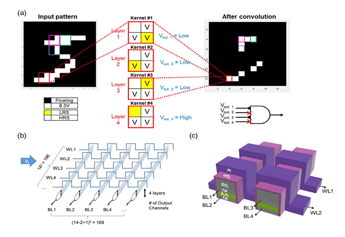
- In contrast to such a SIMO scheme, a MISO scheme could also be represented where there are several simultaneous input vectors, using OR functionality instead. Both schemes can greatly facilitate the simultaneous acquisitions of the multiple input and output vectors, which then eventually improves the system performance. Also, the various types of kernels can be easily adapted based on the S-CBA circuit geometry.
Related Papers :
- Kim, Yumin, et al. "Kernel Application of the Stacked Crossbar Array Composed of Self-Rectifying Resistive Switching Memory for Convolutional Neural Networks." Advanced Intelligent Systems 2.2 (2020): 1900116.
2. Demonstration of graph algorithms using RRAM crossbar array
2-1) Pathfinding algorithm (A*) based on the CBA sneak current- A* algorithm is an algorithm that finds the shortest or optimal path between two specific nodes. The A* algorithm calculates the evaluation function (F), where G(x) is the cost from the starting node to the current node and H(x) is a heuristic function, as shown below and selects a node with the smaller F score.

- The heuristic function estimates the distance from the current node to the destination, and usually, Euclidean distance, Manhattan distance, great circle distance, etc. are used for it. However, this heuristic can only be calculated in a grid-type Euclidean graph, which limits its applicability to various non-Euclidean graphs.
- In this study, we show the implementation of the A* algorithm using a metal cell at a diagonal crossbar array (mCBA) and show that high-quality heuristics can be obtained using the intrinsic physical properties of mCBA based on the graph to CBA (G2C) mapping.
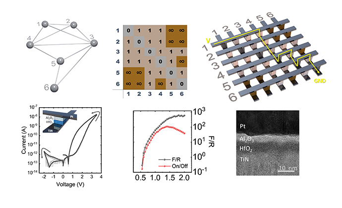
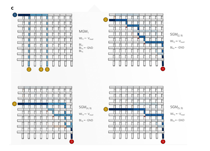
- In mCBA, current flows in a low-resistance path (sneak current). When Vread is applied to the word line corresponding to the source node and the bit line corresponding to the destination is GND, the current flows along the shortest path between the two nodes. This 'single ground method (SGM)' current can be used for the heuristic of the distance between the two nodes.
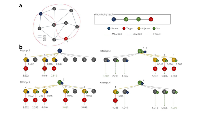
- The above figure shows an example of applying the mCBA-based methods to solve the pathfinding problem in the non-Euclidean graph in Fig. a. In this case, it was attempted to find the shortest path (involving the least weights) from node 1 (source) to node 9 (target). This algorithm aims to find the minimum F score at every attempt. The detailed F explanation is given below.
- When examining Fig. a, node 1 was identified to be directly connected to nodes 2, 4, and 5, involving costs of 2, 3, and 2, respectively, while all other nodes are disconnected. These direct connections could be identified first by the MGM method shown in the upper left of the Fig. c, where the WL1, corresponding to source node 1, was biased, and only BL2, 4, and 5 showed the current flow of 7.45, 1.90, and 7.45 pA, respectively. These currents were converted to the costs via the following Eq (1):
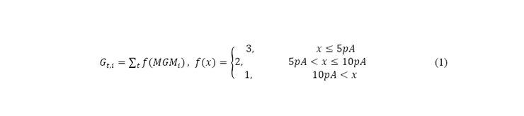
- , where Gt,i is G score at attempt t, MGMi is the MGM output current of node i, and f(x) is a step function that outputs a weight according to the value of MGM.
- These 2, 4, and 5 nodes comprise the adjacent node (in yellow color in attempt 1 in Fig. b), and the small added numbers at the lower right indicate the parent node. In the next step, the estimated costs of the possible connection between these adjacent nodes and the target node are identified by the SGM method, as shown in Fig. b SGM2,9, SGM4,9, and SGM5,9. From the estimated current at BL9 for the three inputs at WL2, 4, and 5, the SGM result for the three nodes were converted to the H score of 1.602, 1.046, and 0.846, respectively, using the following Eq (2):

- , where Ht,i is the H score at attempt t, a is the scale factor to match the scale with Gt,i, SGMi,j is the SGM output current of source i to target j, and k is the weight factor to adjust for the tradeoff relationship between speed and accuracy.
- Lastly, the total score F at attempt 1 (Ft,i = Gt,i + Ht,i) for the three probable paths are 3.602, 4.046, and 2.846, respectively (k = 1.5 in this case), indicating that the path from the node 1 to the via node 5 has the lowest score (shortest distance to target node 9 at the moment of attempt 1). The next step is to find the optimum node next to node 5, which can be performed using the similar sequential MGM and SGM where the via node 5 (in green color in attempt 2 in Fig. c) now corresponds to the biased WL5. In this MGM, the BL1 is excluded by floating it because node 1 is the parent of node 5. The MGM and SGM results indicated that the connection to the target node 9 via node 6 has the lowest F score of 3.027. Therefore, the next attempt (attempt 3 in Fig. a) must start from node 6 and find the connections to node 9 via MGM and SGM. When the MGM was performed at attempt 3, it was found that node 9 was directly connected to node 6. However, it was not necessarily guaranteed that the direct connection between nodes 6 and 9 involved the least F score. In fact, it was noted that the F score for path 1→2→9 is the lowest at attempt 3, 3.602, so it should be checked if the path involving node 2 as the via node has an even lower F score. Attempt 4 in Fig. a shows the result. The MGM and SGM using the biased WL2 indicated that the eventual F score for path 1→2→3→9 was 4.285, which is higher than the F score of 4.000 for path 1→5→6→9. Therefore, it could be concluded that 1→5→6→9 determined by following the parent node of 9 is the least score path.
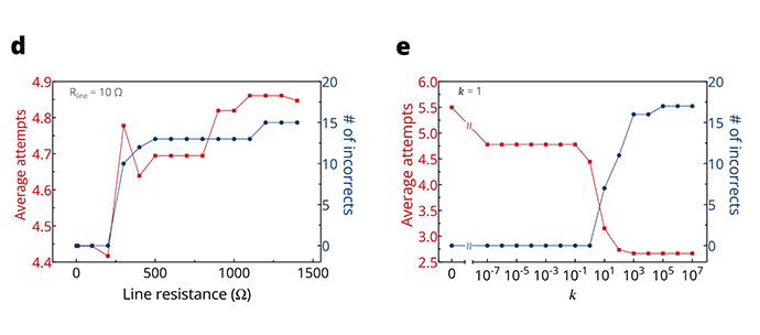
- There could be 72 combinations of source and target nodes in this graph (9C2), and the described MGM+SGM methods identify all the shortest paths between them. However, several factors affect the performances. When the weight factor k is too small, the average number of attempts for all cases increases while the incorrect estimation is low. However, if the shortest path is not required in all cases, k can be adjusted to obtain inaccurate but fast results (Fig. d). In contrast, the lower the wire resistance, the higher the correct estimation and the lower the average attempts (Fig. e). The tradeoff between speed and accuracy can be adjusted by analyzing these factors, and the optimum condition required for mCBA can be identified. The software can perform similar pathfinding work using the A* algorithm. However, this process involves the transformation of the non-Euclidean graph to the Euclidean graph, which requires additional computation costs and may not always be feasible.
3. Demonstration of the artificial neural network with memristive hardware
- The crossbar array (CBA), which uses ReRAM can accelerate the multiply-and-accumulate (MAC) operation by a single-step physical calculation. A large-sized CBA with a selection device, for example, by exploiting one selector and one ReRAM (1S1R) stack, is preferred to maximize MAC operation efficiency. Although several challenges that need to be overcome to use 1S1R CBA practically include IR drop effects, no study has estimated these adverse effects (IR drop and selector nonlinearity) simultaneously in a quantitative manner. In this study, an analytical model that calculates the read margin (RM) and writes margin (WM) of 1S1R CBA was presented. In addition, an analytical circuit model (the ΔV1,N model; the voltage across the selected cell) was provided, which accurately calculates the deviation of the cell bias voltage from the desired value during the worst-case MAC operations, where different voltages are simultaneously applied to all WLs. The proposed analytical model could estimate the maximum accuracy degradation in the MNIST image classification through the involvement of the unintentional voltage drop, as shown in the figure below. The simulation results demonstrated that the model could be used to design better hardware neural network.

Related Papers :
- Kim, Jihun, et al. "In-Depth Analysis of One Selector-One Resistor Crossbar Array for Its Writing and Reading Operations for Hardware Neural Network with Finite Wire Resistance." Advanced Intelligent Systems (2021): 2100174.